A valve ball may look perfectly polished, yet its surface can still contain microscopic peaks and valleys. These small features influence sealing, torque, leakage, wear, and service life. In demanding applications, a few micrometers can change how the ball contacts its seat. That is why is surface roughness critical for valve ball performance, especially under pressure, temperature variation, and repeated cycling.
Controlling roughness begins with material selection, machining, grinding, and polishing. Each stage leaves a different surface pattern. For example, an uneven grinding mark may create a leakage path across the sealing line. A rough surface can also increase friction, trap particles, and damage soft seat materials. Excessive polishing is not always better. It may remove beneficial texture or create dimensional problems.
Reliable control requires measurement, not visual judgment. Engineers commonly inspect roughness with calibrated profilometers, using parameters such as Ra, Rz, and material-specific limits. The measurement direction matters because machining marks may be directional. Clean handling is equally important. A fingerprint, abrasive residue, or small metal chip can distort inspection results or affect final assembly.
Practical experience shows that the target value must match the valve design. A floating ball valve may need different surface control from a trunnion-mounted design. Coating thickness, seat material, pressure class, and fluid cleanliness also matter. There is no universal “smoothest is best” rule. That assumption deserves reconsideration. This guide explains how to define, measure, and maintain suitable roughness for dependable valve ball performance. It also examines common production mistakes, because real manufacturing rarely follows a perfect laboratory process.
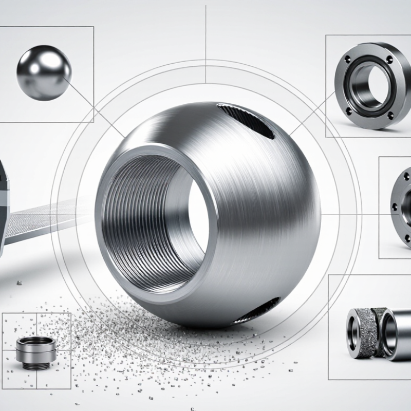
Set Typical Ra Targets of 0.1–0.4 μm for Metal-Seated Valve Balls
Metal-Seated Valve Ball Performance: Control Surface Roughness
For metal-seated valve balls, a typical Ra target is 0.1–0.4 μm. This range supports reliable contact between the ball and seat. Smoother surfaces can reduce leakage paths, friction, and abrasive wear. However, Ra is not a magic number. A ball may meet the target yet contain deep scratches or uneven waviness. These defects can still damage sealing performance during repeated cycling.
Production teams should measure several zones across the ball, not only one convenient spot. Use a calibrated stylus or suitable optical instrument with documented settings. Record the cutoff length, measurement direction, material condition, and final result. Polishing and lapping should remove machining marks without changing ball geometry. Check roundness as well. A very smooth but poorly shaped ball can perform badly.
Tips: Set 0.1–0.4 μm as a practical starting range, then confirm it through torque, leakage, and cycle testing. Clean the ball before measurement. Even a small particle can distort readings. Inspect the seat and ball together, because their surface finish must work as a pair. In some applications, a tighter Ra value may help; in others, it may add cost without improving service life. Review the evidence before tightening the specification.
Relate Surface Finish to API 6D and ISO 5208 Leakage Classes
How to Control Surface Roughness for Valve Ball Performance?
API 6D and ISO 5208 do not treat surface finish as a leakage class by itself. They evaluate valve performance through controlled pressure tests and allowable leakage. ISO 5208:2015 defines six leakage rates, from Rate A, with no visible leakage, to less strict classes. API Specification 6D links valve testing to defined acceptance criteria and documented procedures.
A smoother ball usually reduces friction, particle retention, and damage to soft seats. In many shop applications, engineers target a ball sealing surface near Ra 0.2–0.8 μm. This is a practical range, not a universal requirement. Seat material, pressure, temperature, and fluid cleanliness can change the result.
A mirror finish is not automatically leak-tight. Poor sphericity, coating damage, or misalignment can still produce leakage during an ISO 5208 test. That detail is often underestimated.
Tips:
Measure roughness at several points, not one convenient spot. Record the cutoff length and instrument calibration. Check the ball and seat together. Then perform the specified pressure test. If a valve achieves Rate A once, do not assume long-term performance is proven. Repeated cycling, thermal movement, and debris exposure deserve separate evaluation. Engineers should also review API 6D documentation, because the exact test medium, duration, and acceptance method affect reported results. Some workshop records remain incomplete. That is a quality risk.
Measure Ra and Rz Using ISO 4287 and Calibrated Profilometers
How to Control Surface Roughness for Valve Ball Performance?
A valve ball can look mirror-bright and still seal poorly. Surface measurement must replace visual judgment. ISO 4287 defines Ra as the arithmetic mean profile deviation. It defines Rz as the mean maximum profile height across sampling lengths. These values reveal different defects. Ra shows general texture. Rz exposes deeper grooves that may cut seals or create leakage paths.
Use a calibrated contact profilometer with a diamond stylus. Verify calibration with a certified roughness specimen before inspection. Keep the probe perpendicular to visible machining marks. Measure several locations around the ball, including the sealing band and port edge. A practical trial may specify Ra ≤ 0.40 μm and Rz ≤ 3.2 μm. These values are examples, not universal limits. Confirm them against the valve design, fluid, pressure, and seal material. ISO 4287 and the NIST Engineering Statistics Handbook both stress controlled measurement conditions. Small setup errors can change the result.
Tips: Record cutoff length, evaluation length, stylus force, and measurement direction. Compare at least three traces per critical zone. Do not average away one unusually high Rz value. That “outlier” may represent the real failure mechanism. One weakness remains: operators often measure flat coupons, not the curved ball surface. The method is convenient, but not fully representative. Recheck questionable parts after polishing, cleaning, and final coating.
How to Control Surface Roughness for Valve Ball Performance? - Measure Ra and Rz Using ISO 4287 and Calibrated Profilometers
| Surface Finish Class |
Typical Valve Ball Application |
Maximum Ra
(µm) |
Maximum Rz
(µm) |
Recommended Cutoff
λc (mm) |
Evaluation Length
ln (mm) |
Recommended Measurement Control |
| Precision sealing |
Metal-seated ball and seat contact surfaces for low leakage service |
0.20 |
1.60 |
0.08 |
0.40 |
Use a calibrated stylus profilometer; measure at least three angular locations and report the highest result. |
| High-performance sealing |
Soft-seated valve balls requiring reduced friction and consistent torque |
0.40 |
3.20 |
0.08 |
0.40 |
Maintain consistent traverse direction and contact pressure to improve repeatability. |
| General process control |
Machined ball surfaces outside the primary sealing band |
0.80 |
6.30 |
0.25 |
1.25 |
Take measurements after final machining, polishing, coating, or lapping—whichever is the last surface operation. |
| Coarse functional surface |
Non-sealing areas where surface texture has limited effect on valve performance |
1.60 |
12.50 |
0.80 |
4.00 |
Use only where permitted by the design specification; verify that tool marks do not interfere with sealing or coating adhesion. |
Measurement and Acceptance Data
| Inspection Item |
Recommended Requirement |
Example Result |
Status |
| Arithmetic mean roughness, Ra |
≤ 0.40 µm for high-performance sealing surfaces |
0.32 µm |
Pass |
| Maximum height of roughness profile, Rz |
≤ 3.20 µm for high-performance sealing surfaces |
2.75 µm |
Pass |
| Measurement points |
Minimum three evenly distributed locations on the sealing band |
Four locations inspected |
Pass |
| Calibration verification |
Profilometer verified with a traceable roughness reference before inspection |
Verification completed; deviation within ±5% |
Pass |
| Surface condition |
Clean, dry, free from abrasive particles, oil film, burrs, and visible damage |
Clean and free from visible defects |
Pass |
Measurement terms Ra and Rz are reported as profile parameters in accordance with ISO 4287. Actual acceptance limits, cutoff length, evaluation length, measurement direction, and sampling locations should be confirmed against the applicable valve drawing or purchase specification.
Control Lapping and Polishing Through Ra Checks After Each Pass
How to Control Surface Roughness for Valve Ball Performance?
A valve ball can look mirror-bright and still fail a demanding seal. Surface roughness must be controlled during lapping and polishing, not judged only at final inspection. After each pass, clean the ball carefully and measure Ra with a calibrated instrument. Use the same sampling direction, contact pressure, and evaluation length each time. Consistent methods make trends visible. A sudden Ra increase may indicate worn abrasive, uneven pressure, contamination, or poor alignment. Do not polish blindly. More passes can round edges or create waviness.
Tips: Record the Ra value, abrasive grade, pass time, pressure, and operator observations. Check several zones, including the sealing band and areas near the stem hole. If one location measures higher, rotate the ball and repeat the reading before changing the process. A single reading can mislead. Check temperature too, because thermal expansion may affect repeatability. This step is often skipped.
Experienced technicians compare measurements with visual inspection and contact-pattern results. Ra is important, but it does not reveal every defect. Scratches, pits, embedded particles, and waviness can damage sealing performance despite an acceptable average value. Set an internal limit for each finishing stage, based on material, geometry, and service requirements. Stop when the target remains stable across repeated checks. I have seen teams chase a lower number and lose dimensional accuracy. That lesson deserves attention: smoothness matters only when the ball remains round, clean, and functionally precise.
How to Control Surface Roughness for Valve Ball Performance?
Control lapping and polishing through Ra checks after each pass.
Surface roughness is shown as arithmetic average roughness, Ra, in micrometres (µm), measured at three representative valve-ball zones after each process pass. The polishing target is Ra ≤ 0.20 µm across all checked zones. Lapping removes larger surface irregularities, while final polishing reduces the remaining micro-peaks. Form, waviness, roundness, and dimensional tolerances should be verified separately.
Validate Ball Performance with API 598 Seat Tests and Leakage Records
How to Control Surface Roughness for Valve Ball Performance?
A valve ball may look mirror-smooth, yet microscopic machining marks can create a leakage path. Surface roughness must match the seat material, pressure rating, and service conditions. In practical inspections, technicians should check the ball after machining, polishing, cleaning, and assembly. A roughness reading alone is not enough. Scratches, dents, trapped particles, and uneven contact can change sealing performance.
API 598 seat tests provide a controlled way to verify the finished valve. Test personnel should confirm the pressure medium, test direction, stabilization time, and calibrated instruments before testing. During the test, observe the seat area carefully and record visible leakage, pressure loss, test duration, and acceptance results. These records connect surface condition with actual performance. A smooth ball does not guarantee zero leakage. That assumption can fail.
Tips: Keep roughness readings beside inspection photographs and batch records. Record the instrument identification and calibration status. Clean the ball and seat before testing; one small particle can distort the result. Repeat a failed test only after identifying the cause. Repeating it without investigation weakens confidence. Our first inspection may also miss a shallow scratch, so independent review is valuable. API 598 records should be complete, readable, and traceable to the valve.
Conclusion
Controlling surface roughness is essential to achieving reliable valve ball performance, especially in metal-seated designs. Typical Ra targets of 0.1–0.4 μm can help balance sealing efficiency, wear resistance, and operating torque. The question “why is surface roughness critical for valve ball performance” can be answered by its direct effect on contact uniformity, leakage paths, friction, and service life. Surface finish should also be related to the required leakage classes defined by API 6D and ISO 5208, ensuring that manufacturing targets support the intended valve performance.
Accurate verification requires measuring Ra and Rz according to ISO 4287 with a calibrated profilometer and suitable measurement procedures. During lapping and polishing, operators should check the surface after each pass to prevent over-processing and identify inconsistencies early. Final validation should include seat tests performed in accordance with API 598, supported by complete leakage records. This combination of defined roughness targets, controlled finishing, documented measurement, and functional testing creates a repeatable process for producing dependable valve balls.
 RPZ Valve